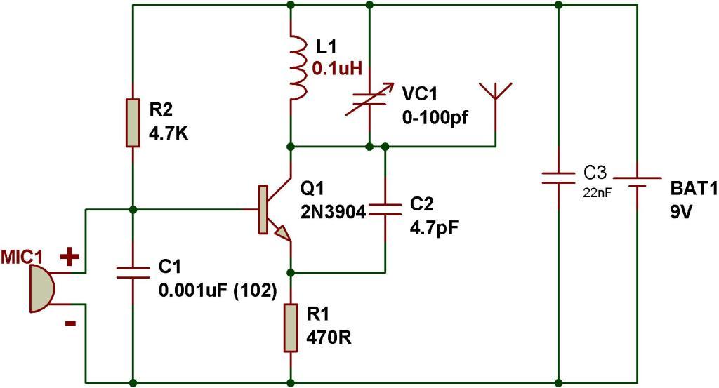


The coil is made of 5 turns of 1mm thick super enamelled copper wire, with 7mm diameter. C2 value could be tweaked for achieving even better response from the circuit. Insert the coil leads as deep down the PCB as possible in order to make it tightly hugging the PCB. This stepped up potential attributes the circuit with a rather longer range of transmission.įor an improved performance make sure the coil and the capacitor are positioned as close as possible. The circuit basically makes use of the “Q factor” of the tank network achieved from the coil and the capacitor for generating a relatively high voltage. Incorporating Q Factorīelow's another circuit you would like to know about. In the original prototype the coil was created by etching a spiral track layout on the PCB itself, however for optimal gain and performance such etched antenna coil must be avoided and the traditional wire wound type of coil must be employed. The second example below shows another single transistor FM spy circuit that incorporates a tuned circuit or a frequency determining stage in it. The circuit may be expected to work at around 90MHz frequency band. In the course if the coil is subjected to an external vibrational pulse, it’s forced to mount the above explained carrier waves in the air and could be received and retrieved over a standard FM radio positioned and tuned at the same frequency nearby. The procedures take place rapidly generating a frequency across the coil which is transmitted as carrier waves through the connected antenna. This switches OFF the transistor until 22n yet again charges fully. A soon as this happens the transistor switches ON via the 47k resistor forcing the pulse through the inductor which feeds back a negative pulse to the base of the transistor discharging the 22n capacitor. When switched ON, the capacitor 22n inhibits the transistor from switching until it gets charged. The following single transistor FM spy circuit may be understood as follows: The design is void of a frequency determining stage and thus does not come under tuned transmitter circuits (we’ll discuss about these later on in the article).

Surprisingly it does not employ a MIC, rather the antenna coil itself performs a dual function of detecting sound vibrations and also transmitting it into the atmosphere.

L1 = 3 to 4 turns of 22SWG super enamel copper wire, 5 to 7 mm diameter, air corePlease refer the scanned image of the prototype for getting an idea regarding the coil dimensions.
#Fm receiver radio circuits schematic free#
The coil turn distance and diameter may be manipulated a little for optimizing best response over the FM receiver.Ī small antenna in the form of a 3 inches wire may be attached at the shown point for making the “bug” highly responsive and generate distortion free signals. The frequency mainly depends on the positioning and the values of the inductor, C1, C2 and C3. The circuit functions quite like a Colpitts oscillator incorporating a tank circuit for the generation of the required oscillations. The above shown wireless FM transmitter circuit is basically a small RF transmitter built around a single transistor. The sent signals can be received over any standard FM radio, tuned accurately to the respective frequency. Subsequently I am going to discuss more such designs which were selected from other websites online. I will begin with a transmitter which I have actually built numerous number of times and tested it thoroughly. IC 741 Transmitter Using Wire Connection.


 0 kommentar(er)
